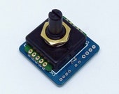
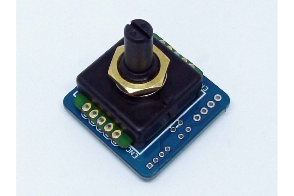
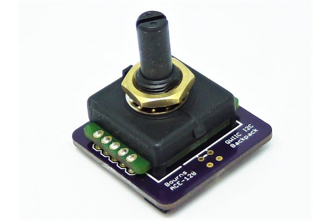
 I’ve started work on motorizing the Dalek dome and came across this nifty rotary encoder. Most rotary encoders are of the incremental type. They give you direction and revolution counts, and may have resolution of only a quarter turn. This one is an absolute position encoder, giving 128 unique binary values on its 8 pins. Other absolute encoders I have seen have one track per bit and are bulky and expensive. This one is one inch square and under $7. It manages this by only having one track with the 8 contacts evenly spaced around it.
The pattern on the track is designed to generate a “gray code” which means that only one sensor will change at any one time. This is important with this kind of encoder as there is no way to ensure that two mechanical contacts will change exactly together. If normal binary is used the value at the exact moment that it rolls from binary 255 (all ones) to the next number (all zeroes) could be any number as some contacts will inevitably lag. With gray code you are either in one position or the next – nothing random.
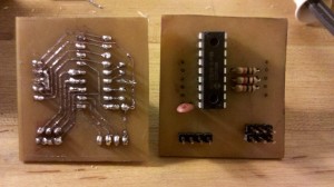
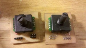
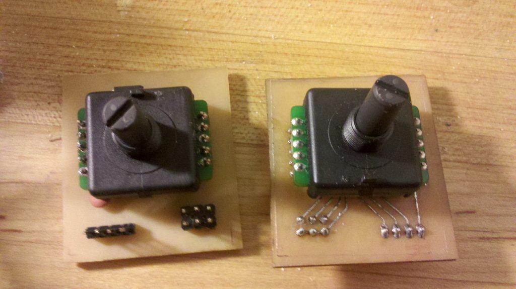
I figured that this would make an ideal position sensor for the dome and eye, and maybe also for the operator’s head. I bread-boarded this out with an MCP23008 IO expander, and wrote an Arduino library to support it. These are attached along with a PCB design for both the MCP23008 and PCF8574 – only the MCP board has been made and tested. These are single sided designs for easy home etching and designed to have the encoder overlap the other components to keep the board small. The encoder can be mounted on the back of the board, though that is weak and difficult to solder, or on the front either into female headers or onto male headers after removing the original pins.
In order to translate the gray code into a useful number the sketch needs a lookup table. This is provided in binary form in the datasheet. Analysis of this shows the 128 bit pattern is offset 16 bits from one pin to the next, so with some computation I was able to generate alternate tables for mixing up the wiring between the IO expander and the encoder, which makes single sided PCB design possible. This is done in an included example sketch, reading the alternate mapping from the serial monitor. The 256 byte mapping table is stored in PROGMEM. Use whichever include file matches your pinout.
A second example sketch displays the raw pins, the lookup table output, and the current result relative to the current zero in signed and unsigned values.
Public methods
public:

// constructor takes relative i2caddr and pointer to PROGMEM map table

// example: ACE128 myACE((uint8_t)0, (uint8_t*)encoderMap_12345678);

// see make_encodermap example sketch for alternate pin mappings

ACE128(uint8_t i2caddr, uint8_t *map);

void begin(); // initializes IO expander, call from setup()

uint8_t upos(); // returns logical position 0 -> 127

int8_t pos(); // returns logical position -64 -> +63

void setZero(uint8_t rawPos); // sets logical zero position

uint8_t getZero(); // returns logical zero position

uint8_t rawPos(); // returns raw mechanical position

uint8_t acePins(); // returns gray code inputs

void reverse(boolean reverse); // set counter-clockwise operation


17 Responses
thanks for this! Was considering buying one of these encoders – seemed the best value for resolution i could find. With your code, is it possible to count revolutions – i.e. continually increasing numbers? I’m guessing it’s catered for by the reverse function?
This does not count revolutions. It gives you a number from 0 to 127 or -64 to +63 representing where in a single revolution the position is at. The reverse function multiples the result by -1. The zero functions let you offset the zero point in software so you don’t have to find that unmarked spot in hardware. So it is not really suited for something that revolves lots of times (like an axle) but better suited for something that moves in a part-circle and you want to know where it is – like a joint in a robot arm, or a Dalek dome or eye stalk. Or your head.
If you were polling it frequently enough I suppose you could count revolutions. All my library does is tell you what position it is at when you look at it, and allow you to map that with a logical zero position, or reverse the numbering. You could use that to count revolutions (and partial revolutions with about 3 degrees definition) but you’d have to write your own program for that.
I advise against using this for constant rotation. It is rated for only 50,000 revolutions and 120rpm. 50,000 sounds like a lot, but at max speed that is about 8 hours.
Position, not revolutions. There are many other encoders designed for revolution counting.
I was considering buying this one too for it’s high resolution and low cost. However, 1 square inch is a bit too big for my application, though I still haven’t found a smaller absolute encoder with the same (or better) resolution. Do you know any?
Considering how much they have in there, I’m not sure how they could make one smaller with 8 contacts in it. I would try contacting the manufacturer and see if they know of any.
Can you make this work for you?
http://interface.khm.de/index.php/lab/interfaces-advanced/rotary-positionsensor-mlx90316/
That would be much easier to mount to the motors – gluing a magnet to the end of the shaft does not require a lathe. For the head-following application I think I would stick with the Bourns gray-code option, but only because it provides the mechanical components for keeping the rotating part in line with the sensing part. very interesting, thanks!
Thanks for this – very useful!
Do you have a schematic for the expander board please?
I did originally upload some files to github, but later I took them out. I can’t remember why. Anyway look in https://github.com/arielnh56/ACE128/tree/50316d257aa4d9c50896ec05b7193502c83cd7b2/eagle/ACE128
Diese Waschmaschinen sind große Reinigungsanlagen, die viel Personal mit technischem
Wissen zur Bedienung benötigen.
Thanks, this is all very useful! Is there a way to use your library without using an I2C expander, but instead just the arduino pins?
also, is it possible to connect 2 of these encoders on the same arduino uno or does that not work with this setup of i2c communication?
Yes, in fact Fred has three:
The I2C bus also talks to the remains of a WII nunchuck for head tilt, and a keypad for control input. Now that LCD displays got cheaper, I’ll be adding one of those too.
The library as it stands assumes I2C, as the device itself uses 8 pins, which would leave you with pretty much none left to do anything else with – unless you are on a mega. The I2C chips are cheap and the PCF8574 is commonly used in LCD backpack modules very cheap e.g. here
It would not be too big a lift to map your multiple Arduino pin states into a single byte, then use the mapping table code to pull out the value. But why? I2C is so much less wires.
Is the second circuit, the one using the PCF8574, only for using this without an arduino/with just an LCD output? i.e. can I hook up the encoder straight to an arduino?
I ask because your Eagle Schematic is kind of confusing without any notation or component values.
The PCF8574 is just an alternate chip to the MCP23008. It still hangs off the IIC bus. Both circuits just wire the 8 data pins on the encoder to the 8 pins on the chip. The rest is standard i2C wiring for those chips – see the datasheet or the rest of the internet for details on that – that’s what I do! Getting the pins on the chip to wire to the encoder in the same order they appear on the datasheet on a single sided board is pretty much impossible. The mapping table generator lets you wire it anyway you like and it is fixed in software.
You can now get PCF8574 in a module very cheap. These modules are sold as backpacks for LCD displays. The pins don’t line up with the encoder but it would be easy to make up cables to patch between them. When I did these circuits these backpacks were quite expensive, but now they can be had online from China for under $1.50, and I was looking for an excuse to dip things in acid.
You could hook it up straight to the arduino but you would use so many precious pins (8). I needed to run three of these on one arduino, plus two PWM motor controllers, limit switches, keypad and some LEDs. On an UNO. My code does not support this option.
The components are the standard used with these chips anywhere. I think there is the little cap on the power pin and then pullup resistors on the address pins.
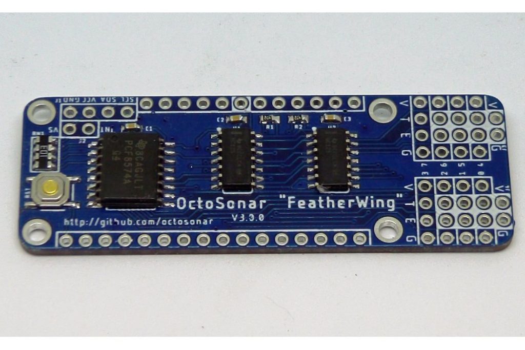
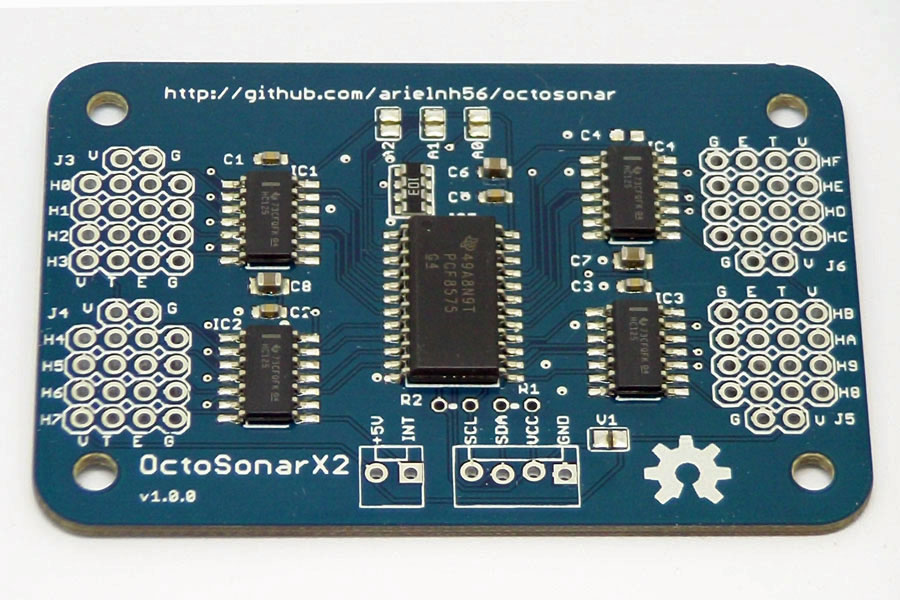
I never actually built this with PCF8574, but I have used this chip more recently on my octo-ultrasonic reader. The little cap there says 104 on it, and I hardwired the address pins. For I2C (IIC?) in general there are rules for where and what resistors you need on the two lines for pullup. I thing I usually put those on the arduino end so I don’t have to worry about them on the peripherals. PCF8574 is easier to code, but is not so versatile at writing – but is should work great for read-only applications like this.
Thanks for reading, sorry for the delayed response. This is an intermittent hobby.
Hey, Great tutorieal. I am interested i using this encoder aswell, however the lack of info on the datasheet turned me off.
If you would not mind I have a couple questions:
-Is there a Vcc? I do not see how the encoder gets power.
-If I can afford to use 8 pins, can the 8 pins of the encoder be hooked straight to an arduino, and simple read the pin states directly? (then convert from grey to bin to dec of course)
Thanks!
I thought I responded to this ages ago – apparently I didn’t hit “send”.
1) The encoder itself is an unpowered mechanical device, similar to a rotary switch. It has two common pins in the middle of each side connected to each other which you would wire to either high or low logic, depending on your preference.
2) Yes. In fact I am playing with doing this with an on-board ATtiny841. Code at https://github.com/arielnh56/ace128tiny