The Bourns ACE-128 Absolute Contacting Encoder is a mechanical knob providing an 8-bit gray code output with 128 unique values per rotation. When I first started using them I assumed there was a single track on the rotating part and 8 little contacts attached to the pins. The track on the rotating part would match the 128-bit pattern you can read vertically from the datasheet. If you check the table closely, you will see that each vertical colummn is offset 16 positions – one eighth of a rotation from the next.
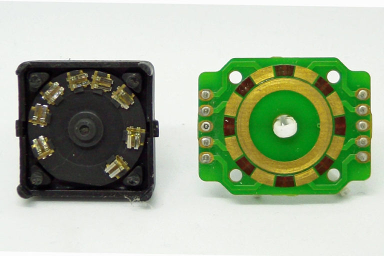
One day, while testing my backpack modules, I came across a unit that was operating intermittently and felt loose. I suspect it was missing an internal spring washer to maintain pressure on the contacts. Rather than going through the hassle of trying to return it, I decided to open it up and see what was inside. What I found was exactly not what I expected. It is simpler and smarter.
The circuit board has no contacts attached to it. Instead there are two tracks. The inner track is continuous and connected to the common/ground pins. The outer track is gapped evenly – 8 sections of equal size with gaps between of equal size.
With 128 positions in the circle, each pad or gap represents 8 positions.
On the rotating part there are contacts which will bridge between the inner and outer tracks. These contacts are spaced in a very special way.
If we observe the binary track from pin 1 in the datasheet:
11000000001111111111000000001111111000000001111111111111111111111111111100000000111111000000001110000000011110000000011000000001
If you look closely you will see that while the ones appear to be in randomly sized blocks, the zeroes are always in blocks of 8. As we are grounding the common pin, the zeroes are where any contact is touching a pad, the ones are where no contacts are touching. The contacts are spaced enough apart that only one can touch any pad at any time. To get the gray code – only one contact transitions on or off at any position change – the contacts need to be spaced in such a way that this occurs.
With 8 positions for each pad/gap and 8 contacts this works as follows.
For each pin, take the offset position and divide by 8.
The remainder – the modulus – should be different for each contact.
The offsets of the first zero in each block are 2, 20, 35, 72, 86, 97, 109, 119.
The moduli of these values are 2, 4, 3, 0, 6, 1, 5, 7.
Which is all the values from 0 to 7.
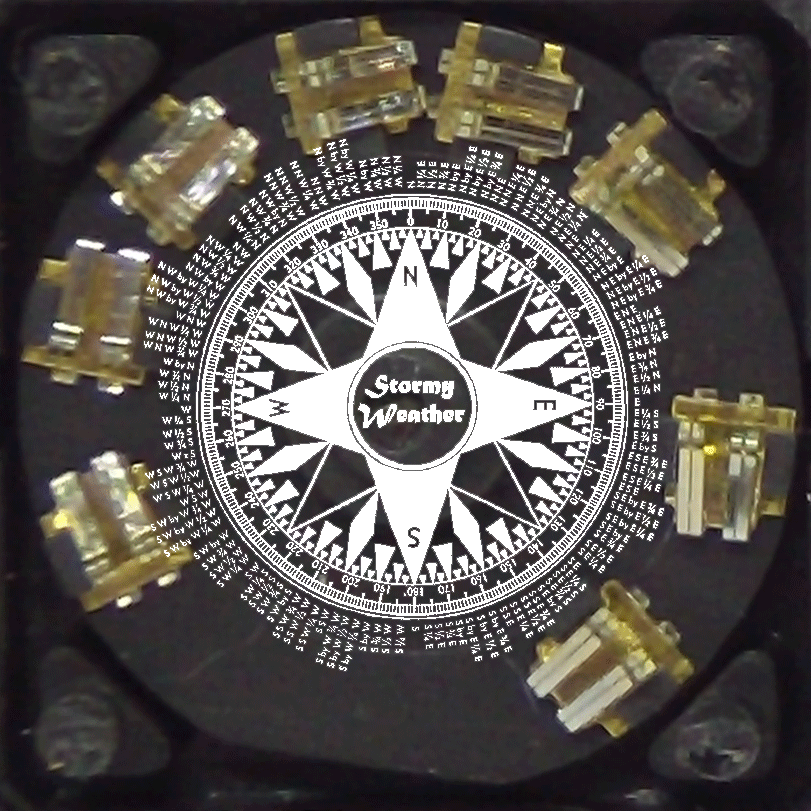
Before I figured this out I thought it was to do with the size of the gaps between the contacts, so I mapped it all out against a 128 position compass rose. This was entertaining but ultimately not the right approach.
I’m very impressed with the ingenuity that went into this sensor.
My I2C backpack modules are available on Tindie, if you want to integrate these into your next Arduino or Raspberry Pi project.
4 Responses
How do your ACE-128 encoders feel when you turn them? I just got one from Mouser, and it has a bit of a gritty feel to it. If that’s how they all are, ok, but if they’re supposed to have a smooth feel, I might send it back for a replacement.
There is a slightly gritty feel, that is a good word for it. This is the little contacts running on and off the PCB contacts.
I did have one once that was smooth and loose, but it was broken – missing an internal spring washer I think, so I took it apart to see how it worked.
I’m running the ace128pintest with direct wire to my arduino uno and I uncommented the
#define ACE128_ARDUINO_PINS but I get this error
Compilation error: no matching function for call to ‘ACE128::ACE128(int, int, int, int, int, int, int, int, uint8_t*)’
what am I doing wrong? thanks for your help
That should work. It works for me.