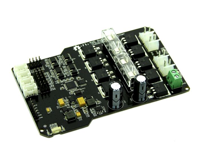
The Seeed Studios Hercules Dual 15A 6-20V Motor Controller came with the Hercules Robot from Robotshop and seems to be a very well designed and made piece of gear. Robotshop do not list the card as a separate product, but it is listed at the SeeedStudio site. It provides all the electronics you need for a high powered Arduino robot on one compact card.
It has built in power regulation from 6V up to 20V, so draws power directly from the motor power supply.
It uses IR2104 driven MOSFETs, which allow high efficiency power usage. This technology does not waste a lot of heat so no heat-sinks are required.
The two H-bridge circuits are have fuse protection and each has two motor connectors. The web pictures indicate that motor cables are supplied with the card.
The Seeed Wiki Page has a lot of information, but much of the text is confusing or incorrect. In particular the MotorDriver_4WD.zip linked to is not the current code, and the forum users indicate that it does not work. The current code is on github and is linked to from the store page. The schematic download link and the board layout image on the page are must haves.
One other error I found was where it says to select “Tools->Board->Arduino Pro or Pro Mini (3.3v, 8MHz) w/ATmega168”. This should be the Atmega328, ours would not load with the 168 setting. I have my doubts about the 8MHz/3.3v setting too as the docs indicate everywhere this is a 5V TTL board, and my magnifying glass shows the processor is an Atmega328P-AU1340 and the Xtal is a 16MHz chip. It runs fine as a 328/5V/16MHz Pro, and that is the setting we are now using.
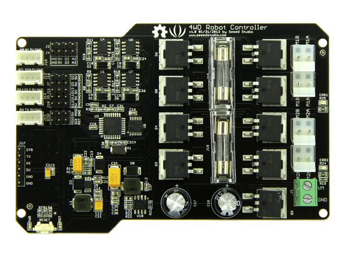
This is not an Arduino with a built-in motor driver, it is a motor driver with a built-in Arduino. It is not optimized for bread-boarding and experimenting, but for embedded use. This makes it ideal for building into your robot project as it is small and self-contained, and has industry standard peripheral connectors, but not ideal for your first Arduino tinkering experience. As such the layout and connectivity options are very different.
- No USB interface is included on the board, so a separate USB to Serial converter is needed. The robot kit includes a UartSBee V4 and a ribbon cable for this, which connects to a 6-pin header. This is a reasonable and common feature on embedded boards.
- Arduino shields will not fit. You can probably wire them up, but actually plugging in directly is not an option. All of the standard pins that are not used by the motor controller itself are available in connectors, except AREF, so you could make a proto-shield into an adapter plate if you really need this.
- The two Arduino interrupt pins D2 and D3 are broken out into 4-pin encoder headers, which include the A2 and A3 pins respectively for the B channels on 4-wire encoders.
- Four Grove-style connectors are included , each has these two pins plus 5V and GND:
- TX/RX/5V/GND (a.k.a. D0/D1)
- D11/D12/5V/GND (a.k.a. MOSI/MISO)
- SCL/SDA/5V/GND (a.k.a A5/A4)
- A0/A1/5V/GND
- Five 3-pin headers for servos, each has one signal pin plus 5V and GND. Pins are: D11, D12, D13, D3, D2. Note that four of these five duplicate pins on the Grove or encoder headers, so pick and choose.
- There is no integral D13 LED as on the Arduino, so “Blink” does nothing unless you wire your own LED.
- The schematics show the usually unconnected A6 pin is set up to read the supply voltage via a resistor tap. This works. analogRead(6) * 5.7 works for me. Calibrate this against a multi-meter and adjust for your board.
- The standard ICSP header is included. This includes the only RESET pin available.
- There is a reset button, power LED and reset LED.
- No AREF pin is available. This is wired internally to 5V.
- Voltage regulation is good – my board reads 5.02V on the 5V pins. There are no 3.3V pins.
The supplied software on github (not the zip file on the wiki) is pretty basic, providing PWM forward and backward commands for both motors together and each individually. To make it work you need to rename the folder to remove the trailing “-master” on it, as “-” is not allowed in library names. Some of the examples do not work (motorDriverDemo) as they are from the old zip/wiki library which had a different name.
The software uses a PWM library from Seeed which sets up the high-frequency PWM for quiet motors.
We found that the motors outlets are all wired the same way, so if M1 is left and M2 is right and you command them all forward, the robot spins on a dime. This is easily fixed by reversing the wiring on the motors.
The “DC_Motor” example worked right off, once we actually got it loaded. Use that one.
If you want to use alternate driver code the H bridges are configured as follows:
- M1 Control D4 and D5
- M1 PWM D9
- M2 Control D7 and D8
- M2 PWM D10
- Pull D6 HIGH to enable both bridges. LOW to cut everything off.
As you have two control lines to each H-bridge you have full access to braking functions, not just forward and back. See wikipedia for a good explanation of this.
Software is also supplied to drive stepper motors, but my lack of knowledge on that topic combined with the difficult to read info provided leaves me unable to evaluate it at this time.
In summary, this is a very well designed and manufactured card. I could have used one of these for the Dalek dome, and saved myself a lot of soldering. It will be my first choice for any future 2-motor projects that come up.
7 Responses
Hi
Thank you for this post. I am in the process of learning to use this robot and adding features.
So far added;
1) an RGB display to show input data and
2) “reversed the leads in software to address the pin problem with the motors” I don’t like changing the hardware to sort out a software problem.
Now I would like to read the motor “encoders” to get feedback on the speed. I have looked but cannot find how to do this, I am prepared to do the work, but have no idea where to start. Are you able to provide any pointers on how to commence my journey?
PS I can provide the above code to you if you wish.
I disagree on the “change the hardware to fix a software problem”. I regard it as a hardware problem if you tell both motors to go one way and one of them goes the other.
It is a question of semantics. Is “forward = clockwise” or is “forward = makes the robot go forward”?. I would argue that the latter makes intuitive sense, so the wiring of the motor did not match the application. I did a similar thing with the Dalek, where we mounted the entire wheelchair assembly in reverse. As its controller treats reverse very differently (slow beep beep beep), I reversed the wiring to match the reversed install. Do the hardware right and the code is simpler. Simpler is good.
As for the encoders, you wire them to the hardware interrupt pins 2 & 3, and then use attachInterrupt to update a timestamp when they trigger. You take the time between two timestamps to calculate the rpm.
A new project I’m working on returns the value in RPM. This is still a work in progress but here’s a relevant snippet (not the whole thing and I can’t guarantee it will compile). It takes the time between two timestamps to calculate the rpm, via an averaging filter. It also records the count for distance measurement.
// rotation encoders on hardware interrupt pins

// these are speed encoders, not direction i.e. 3 wire

#define ENCODER_L 2

#define ENCODER_R 3

#define GEAR_RATIO 36.0

double rpm_l = 0;

double rpm_r = 0;

volatile unsigned long int last_rpm_l, last_rpm_r; // duration between last two pulses in microseconds

volatile unsigned long int last_enc_l, last_enc_r; // timsestamp of last pulse inc micros()

volatile unsigned int enc_count_l, enc_count_r;

double current_rpm_l = 0;

double current_rpm_r = 0;

void setup() {

  last_rpm_l = last_rpm_r = last_enc_l = last_enc_r = 1;

  enc_count_l = enc_count_r = 0;

  pinMode(ENCODER_L, INPUT_PULLUP);

  pinMode(ENCODER_R, INPUT_PULLUP);

  attachInterrupt(digitalPinToInterrupt(ENCODER_L), update_rpm_l, RISING);

  attachInterrupt(digitalPinToInterrupt(ENCODER_R), update_rpm_r, RISING);

  Serial.begin(9600);

}
unsigned long int last_debug = 0;
unsigned long int last_average = 0;
void loop() {
unsigned long int now = micros();
noInterrupts();
if (last_rpm_l < micros() - last_enc_l) { // it's been longer than the last pulse already last_rpm_l = micros() - last_enc_l; } if (last_rpm_r < micros() - last_enc_r) { // it's been longer than the last pulse already last_rpm_r = micros() - last_enc_r; } interrupts(); if (last_average + 100 < millis()) { current_rpm_l = ( current_rpm_l * 0.9 ) + (6000000.0 / (last_rpm_l * GEAR_RATIO)); current_rpm_r = ( current_rpm_r * 0.9 ) + (6000000.0 / (last_rpm_r * GEAR_RATIO)); } if (last_debug + 100 < millis()) { last_debug = millis(); Serial.print(current_rpm_r); Serial.print(" "); Serial.println(pwm_r); } } void update_rpm_l() { unsigned long int now = micros(); enc_count_l++; last_rpm_l = now - last_enc_l; last_enc_l = now; } void update_rpm_r() { unsigned long int now = micros(); enc_count_r++; last_rpm_r = now - last_enc_r; last_enc_r = now; }
I apologize for the late reply on this, when work is busy, the blog gets a bit stale.
well, so much for “
" tags in the comment editor - that's illegible.do a "view source" and you'll find it.
hah! I said “code tags”
Thank you so much for this article.
I just got the Hercules platform after a lot of searching. I knew there was going to be a learning curve, but the a $160 platform with a ~30# payload was just too goo to pass up. I was also impressed by the motor controller, thinking I would use it for expanding in the future.
However, I am totally stumped :( I’m not new to Arduino / robotics and as a software engineer I figured I would figure it out eventually.
Here’s all I want to do – I want to connect a NRF24L01+ 2.4GHz Wireless RF to it without using anything XBee. I’ve done loads of projects with them and various Arduino board so I’ve got loads just laying around. I built my own 6 channel transmitter also. I also don’t want to start going over to everything Grove / XBee.
I’ve gotten to the point I really would rather pay someone the same cost as an XBee RF unit to solve this problem for me. I don’t understand (even if I had to get a grove proto shield, which I’d rather not) how I can connect the NRF24L01+ to the hercules motor controller. If I need to use an arduino – like:
NRF24L01+ -> Arduino -> Hercules
I’m happy with that as I plan to put an arduino on it also. If you have any pointers or feel like $20 would be worth just documenting it out I would be happy to paypal it to you :)
A side / related question – do you know how I could just use my own Arduino to leverage the Hercules motor controller directly? (aka bypass whatever ardiuino is on the board)
-Mike
I answered your other comment first. You can’t access the motor controller directly, and the controller uses up a lot of the Arduino pins. Also you don’t have a standard shield format socket. I’ve never done any xbee or RF stuff, so I have no hints there, but if you are just trying to figure out where to blug it in and the pins you need are not broken out, then they are probably used already – see the schematic.
What we did on the first pass, as we were integrating a gieger counter shield was to use a proto shield with the appropriate female headers and mount that on the top plate, and wire it back to the pins on the board. That thing only needed one pin though. For the next iteration I’m using another arduino (56c with a coupon from banggood.com) to handle all the arduino lots-of-pins peripherals and limiting the function of the embedded arduino to take speed direction and distance commands. It uses PID to keep the wheels to the requested speed, so the master unit doesn’t have to do all that stuff as well as figuring out where to go. Communication between the two is a serial messaging library. I haven’t touched it in months so I forget the details right now.
Thank you so much for the replay and the details. I’m sorry it has taken me so long to get back.
I found this which has helped me out tremendously:
http://www.billporter.info/2011/05/30/easytransfer-arduino-library/
And I got an ‘adapter’ which basically turns the grove connectors into standard pin inputs:
https://www.amazon.com/gp/product/B01CNZ9EEC/ref=oh_aui_detailpage_o07_s00?ie=UTF8&psc=1
I wish I found that cable earlier. I was actually soldering cables directly to the Grove pins which was a mess.
Then – just cabling from my arduino (with an RF receiver which receives RF values from a joystick I made with an RF transmitter) directly into the grove inputs of the Hercules motor controller I can now send data to the Hercules without special grove modules.
Finally I used the included XBee and programmed the Hercules to take the input data and translate it to motor controls.
I actually haven’t done all this yet – I’ve only sent simulated data down. But I have proven it can be done. The EasyTransfer I2C and adapter cables was what I was really missing.
That pic is f’ing AWESOME! Thank for all the info you share – it really helps a lot more people than you probably know.
-Mike